Keeping control with variable flow
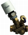
Fig. 1: Stable flow in systems with variable-speed pumps can be achieved using pressure-independent control valves, such as the Danfoss AB-QM — shown here fitted with an actuator.
Rather than delivering buildings that are more comfortable and use less energy, variable-flow systems can do quite the opposite without care in the selection and choice of control valves. Martyn Neil explains.In building services, variable-flow systems are essential as we strive for both energy efficiency and lifetime value for clients. Cost savings on pumps and piping reductions mean the usage of these systems will continue to grow, but valve sizing requires care The sizing of control valves is all too often described as an art. The reason for is that as hydronic systems have changed valve-sizing calculations have also changed. Variable-flow systems require new calculations, new terminology and, most importantly, new technology. There is one definitive aim when sizing control valves — to find the perfect valve solution for the system. Finding that perfect valve involves understanding the hydronics of the project and recognising the importance of perfect control flow.
Control valve selection The effects of variable flow on the selection of control valves, was not initially realised. A control valve was selected by using the same Kv calculation and the bypass on a 3-port valve blocked, giving a 2-port valve. Unfortunately it wasn’t that simple. This is because our Kv calculation Kv = flow rate (m3/h)/√?P (bar) was based on a constant pressure and a constant Kvs (Kv for a fully open valve and defined as flow in m3/h with a pressure difference of 1 bar), delivering constant flow. However, as sections of the variable-flow system close down, the differential pressure increases, increasing flow and causing overflow in the open circuits. Overflow in a circuit is costly. Unfortunately, traditional control valves make it inevitable. As we size a control valve the Kv calculated almost certainly will not match the Kvs of the nearest appropriate valve. For example, a Kv calculation of 4.5 m3/h would most likely lead to selection of a valve with a 6.3 m3/h Kvs, which in its fully open position would deliver 40% more flow than required at 1 bar pressure difference. As differential pressure increases in our variable-flow system, the valve will permit more flow.
Hunting This excess flow will cause the temperature to overshoot the set-point. Once the room sensor has detected this overshoot, it will close the actuator — causing a sharp drop in flow. The process will repeat itself in a phenomenon described as ‘hunting’ (Fig. 1). Hunting causes the room temperature to constantly fluctuate, creating a major cost to clients in poor environment quality and increased maintenance. Over three-quarters of complaints to building managers are about being too hot or too cold. These complaints are rarely due to people’s differences in preferred temperature but to wide deviations in the room temperature. The solution that more than two-thirds of building managers use to answer this type of complaint is to change the set-point. Lowering the set-point for a cooling system by 1 K increases its energy usage by up to 10%. The solution to the problems of ‘hunting’ and overflow in chilled-water systems lies in the use of pressure-independent control valves.
Pressure-independent control valves

Fig. 2: With too high a differential pressure, traditional control valves will permit overflow, so that the setpoint is quickly exceeded — leading to the ‘hunting’ shown by the red graph. In contrast, a pressure-independent control valve will maintain the design flow, and achieve more precise control (blue graph).
Traditional control valve sizing for constant flow systems involves calculation of Kv and actual pressure drop calculation — plus a check to ensure minimum valve authority is met. This method is complicated and inflexible, as the changes in design flow, circuit pressure and required pressure drops can change the required valve — reducing controllability. This method also relies on having the correct design information. A more effective approach is to use pressure-independent control valves such as the Danfoss AB-QM to limit the flow to the fan-coil terminal and air-handling unit. This flow is not affected by changes in inlet pressure. A diaphragm within the valve keeps the outlet pressure constant, so a constant flow is delivered to the terminal. The added advantage of pressure-independent control valves is that, when fitted with an actuator, they replace the manual balancing valve and motorised control valve with a single valve, thus reducing installation cost. Such a combined flow-limiter and control valve is sized purely on the flow. First note the flow required to the coil, select a valve that can deliver a higher flow and set the required flow as a percentage of the maximum flow of the valve. This procedure gives the exact design flow to the coil and eliminates overflow. Changes in design pressures, and required flows can be easily accommodated. Valves such as AB-QM can be set in seconds, without the use of tools, and are available with test points to enable flow verification for commissioning documentation and trouble shooting. AB-QM valves are extremely compact and are available in sizes from 10 to 100 mm to handle flow rates from 30 to 41 000 l/h.
Control-valve strategy Pressure-independent control valves can be used with any control strategy. The actuator options give a choice of thermic, 3-point control or modulating control. This will work with building-management systems and individual room controls, in the same way as traditional control valves. The actuators can also be used to set the valve by limiting flow. In 3-point control applications, this can be done using a run time limitation. For example, for 70% design flow we give the actuator 70% of its total run time. With a modulating actuator, to achieve our 70% example we set the controller to control between 0 and 7 V of the 0 to 10 V signal.
Conclusion Overflow affects the ability of the control system to achieve the set temperature, but overflow need not be inevitable. Pressure-independent control valves enable fan coils and air-handling units to have the maximum flow set exactly at design flow. Switching a traditional control valve to a pressure-independent type should not be seen as only benefiting the mechanical contractor, by reducing installation cost, but also as benefiting the systems integrator and, most importantly, the client, by improving comfort and reducing energy consumption. Pressure-independent control valves are an essential part of hydronic control in chilled-water applications. They are simple to select and easy to set. They enable a steady pressure, a steady flow and, most importantly, a steady room temperature. Martyn Neil is commercial business development manager with Danfoss Randall Ltd.
Related links:
Related articles: