Mary Rose nears the end of her trip to recovery
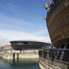
Very few of the 500 000-plus visitors to the Mary Rose Museum in Portsmouth have been behind the scenes to see the engineering services that are playing a crucial role in the final stages of her restoration. Ken Sharpe is one.
The skills and expertise that have been involved in locating the Mary Rose, the flagship of Henry VIII which sank in 1545, have been many and varied. Her remains were located in 1971 in The Solent off Portsmouth, where she was built from 1509 to 1511. It was not until extensive underwater archaeology was completed that she was raised to the surface in 1982.
Since then a major programme of conservation work has been going on — with the ultimate aim of letting the public see the remains in the same space as themselves, rather than cocooned in their own special enclosure.
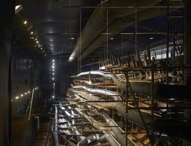
The final stage of that conservation is utilising building-services expertise to permit the final drying out of the hull in closely controlled conditions. This stage is progressing well, and the wall that separates the enclosure (known as the hot box) housing the remaining hull of the Mary Rose is expected to be removed within a couple of years.
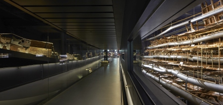
At present, the ship can only be viewed through windows of various sizes. And that view is also obstructed by many runs of textile ducting that delivered the closely controlled air that maintains the controlled environment. Those conditions are a temperature of 19°C ±0.7 K and a relative humidity of 54% ±4%. The aim is to remove 130 t of water that the timbers absorbed during previous stages of the conservation work.
The first stage of that work was to spray the timbers with chilled water for 12 years. The aim was to prevent the timbers drying out and shrinking by anything up to 50%.
Then began a programme of spraying the hull with polyethylene glycol (PEG) to replace the water in the cellular structure of the wood. A PEG with a low molecular weight was used first, followed by one of a higher molecular weight to strengthen the outer layer of wood.
Now the excess water is being removed.
The problem facing consulting engineering Tim Lloyd of Ramboll at Southampton was the high cost and large space requirement for a traditional approach to providing the level of redundancy required to guarantee that the environmental conditions would be achieved — virtually no matter what.
Three air-handling units would have been needed, each one of them capable of the total duty requirement of 25 m3/s. The procedure would be for one unit to be operating, one to be on standby and the third to be available for maintenance.
Contributing to the large size of such units would be an appropriately sized centrifugal fan (the AHUs are 100% recirculation) and heating and cooling coils capable of the entire duty. Such a fan might have occupied 2 to 3 m of the length of an AHU, compared to about 90 cm for the AHUs that were actually used.
 |
| Visitors are still separated from the remains of the Mary Rose by its environmentally controlled ‘hot box’, which will be opened up when the timbers have finally been dried out. (Photo: Hufton+Crow) |
That alternative solution, and you could call it value engineered, comprises three Fanwall units from Eaton-Williams. Air movement is provided by six plug fans mounted, you’ve guess it, in a ‘wall’. Each AHU can meet a third of the total requirement for air movement with the fans running at 80 Hz. If one unit is out of use for whatever reason, the remaining two units can have their fans run at 100 Hz to meet the airflow requirement. There is just one variable-speed drive for all six fans in an AHU.
Interestingly, the failure of a fan in an AHU does not provide, as might be expected, a short-circuit path for air movement. The flow continues to be laminar within the unit. An individual fan is quite light and easy to replace using fans that are kept on site.
Likewise, each AHU has three cooling coils, two of which are adequate for the duty if all three units are in use, with the third called up if one AHU is down or being serviced.
These coils can provide sensible cooling or remove moisture from the air. Dehumidified air is then brought up to the required temperature by heating coils.
A small amount of fresh air is supplied by two small AHUs, about 1 m3/s, direct to the hot box to pressurise it to 2 Pa.
The main AHUs are served by three Airedale Ultima Compact chillers, each with a cooling capacity of 162 kW. Two are duty units, and one is standby. These chillers also meet the other chilled-water requirements of the Mary Rose Museum.
Heat for the heating coils is normally provided by the site’s steam main via a plate heat exchanger. During the summer, however, that task is the responsibility to a pair of Ideal Stelrad oil-fired boilers. Gas would have been too expensive to bring to the plant room, so oil is used instead.
And on the occasions when moisture needs to be added to the air there is a Vapac humidification unit, each with two humidifiers.
The textile ductwork is from KE Fibretec. Some runs are not permeable and serve to transport air to the permeable sections. This ductwork was quick and easy to install — in just three weeks, with the hull still being sprayed with chilled water. It will also be similarly quick and easy to remove when the Mary Rose is put on full public view.
 |
| The flexible ductwork that delivers conditioned air to the ‘hot box’ that contains the Mary Rose will eventually be removed — give visitors unobstructed views. (Photo: Hufton+Crow). |
Professor Mark Jones, head of collections at the Mary Rose Trust, explains, ‘Access, limited space, size constraints and 24/7 reliability were key considerations. The museum cannot be disrupted. We required a robust solution that could offer N+1 redundancy and ease of maintenance.
‘Any plant failure would be detrimental and put undue stress on the timbers. We adopted a “what-if” approach with Eaton-Williams. It was essential that any solution could not be compromised.’
Ramboll was responsible for the design of services servicing the hot box. Tim Lloyd explains that the work included laser scanning of the hull to produce a model with 16 million surfaces, which was then rendered. That model was the basis of an 11-month programme of computerised fluid dynamics to ensure good air distribution and no static areas. The air flows are difficult to interpret, and it is often best explained to be like displacement ventilation in three dimensions — if this were actually possible.
Controls obviously play a key role in such a demanding application. For reliability each of the main AHUs has its own BMS based on a Honeywell Hawk controller, although they can talk to one another. Although the environmental conditions in the hot box were maintained within the required limits, they oscillated quite widely. Much smoother control was achieved using the controllers’ offset capabilities to matched measured RH with actual RH in the hot box.
When the process of drying out the timbers is complete and the hot-box is opened up to the public, the Eaton-Williams AHUs will be linked up to ductwork that has already been installed for that stage of the history of the Mary Rose. But that may be another story.