Outdoor units are the key to VRF system efficiency

Packing the outdoor units of a VRF air-conditioning system too close together can have an adverse effect on the performance and efficiency of the system. Andy Slater of LG Air Conditioning & Energy Solutions explains.
The initial design structure of HVAC systems has to comply with both local and regional strategies such as the Government’s ‘Non-domestic building services compliance guide’, which is based on BS-EN and ISO test standards. At the same time, manufacturer-applied technologies like temperature and humidity sensing dual control, variable heat exchanger paths and active refrigerant control help to achieve efficiency benchmarking and requested life cycle costing.
During specification, data is used from laboratory testing methods. However, variables generally missed during HVAC application can account for a reduction in efficiency compared to those of specification. Appropriate product type selection, location and operational restrictions are mostly overlooked.
Whilst operational, a system adjusts to meet target variables, whether it be superheat, sub-cooling, high pressure and low pressure — to name but a few. Any movement away from these design variables has a significant effect on the output and efficiency of a system. Manufacturers provide installation guidelines for this exact reason — both to maintain optimal operating conditions but most importantly to prevent product failure.
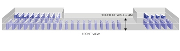
As available space for outdoor plant and planning compliance are becoming more and more restrictive, a greater number of VRF outdoor units are being installed with narrower-than-recommended spacing or grouped internally with ducted discharge air, leading to unplanned recycling of discharge air and rises in operating pressures/ temperatures.
Computational fluid dynamics (CFD) is not generally used in HVAC design as much as it maybe should. By inputting site- and project-specific details into such software, numerical methods can analyse and predict the flow of fluids. The simulation data that is produced can be shown to be less than 2% different from measured data, and be used to provide design proposals that will maintain efficiency and capacity.
 |
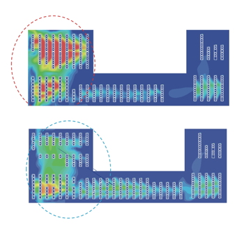 |
| The arrangement of outdoor units at the left-hand end of an large VRF air-conditioning installation led to a CFD analysis predicting them to operate at excessively high temperatures (centre image), which was solved by a simple rearrangement (bottom picture). |
Pressures and temperatures in heat-exchangers are important variables in maintaining specified efficiencies. The effective dissipation of discharge air from outdoor units is paramount to a prolonged efficient lifecycle of a system. The first concern of a unit’s location is that of operation. For example, a heat-exchanger temperature of above 43°C caused by inadequate airflow around the unit would be considered irregular and prevent the system working to design.
A high density of condensers in an area of a roof-top compound could lead to recirculating air raising a heat exchanger’s temperature to 49.5°C and with it an unforeseen point of operational failure of the systems involved. A simple relocation of some systems and change to the organisation of condenser layout within the available compound space would alleviate the potential failure point and regulates the heat exchange temperature to a more appropriate high point of 42.9°C.
Once system operation has been secured, it is important to optimise those variables that will affect system efficiency.
For example, simple miscalculations of louvre design and spacing, can lead to an 8 K increase in condenser-heat-exchanger temperatures and increase energy consumption by approximately 13%. In other words, a 1 K increase in heat-exchanger temperature caused by a site-specific application or miscalculation would lead to a 1.63% increase in energy cost.
The reason is that the system increases its power consumption ratio to achieve a higher condensing temperature to maintain heat exchange with the rising temperature of ambient air. The increased air pressure caused by the louvres’ miscalculated design not only causes a rise in operating temperature but also reduces airflow across the heat exchanger, thereby reducing its heat-exchange ratio and system capacity. This reduction further exaggerates any power consumption ratio increase to the effect of a 0.5% decrease per 1% decrease in air volume flow rate.
It is important to remember that for a VRF system to carry its design potential though to applied installation, even the smallest miscalculated detail can have significant detrimental effects to the operation of the system and, with it, efficiencies and energy consumption.
Focus should not only be applied to the certified data from manufacturers and guidance of automated piping design programmes, but also to the small specifics.
By using 3D modelling to simulate conditions as part of your proposal, potential failures can be anticipated without having to reinstall or create counter measures, guidance for improvements can be given, and much more accurate life-cycle costing applied.
Andy Slater is senior technical, research and development manager for LG Air Conditioning & Energy Solutions.