Design considerations for pressure-boosting sets


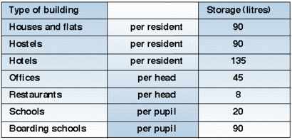
Table 1: The sizing of the break tank that is required to separate pressure-booster sets from mains water can be established using these data.
Three other factors need to be considered. • Ensure the outflow is not greater than the inflow.• Prevent stagnation by ensuring that water in held in storage for as short a time as possible.
• Tank should be constructed in a WRC-approved material. The next step is to correctly size the booster pump or pumps by establishing: • required flow rate at peak demand;
• required outlet pressure at appliance;
• static height;
• pipework friction losses;
• suction conditions;
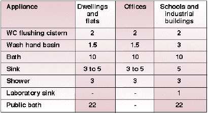
• voltage. A common error when sizing a booster set is to over-estimate the system demand by assuming that all appliances will run simultaneously, which is very rarely the case. Therefore we should calculate peak demand as a percentage of the maximum, using either actual usage figures or loading units. Do we now have the information we need to work out the desired flow rate? There are at least five different ways of calculating the required flow rate for water-booster systems, so using loading units as the calculation vehicle, maybe an easier method (Table 2).

Table 2: Sizing a break tank using loading units immediately allows for the fact that not all outlets will operate at the same time.
Another benefit of loading units is that it allows for the diversification factor that not all outlets will operate at the same time. There are some exceptions, such as irrigation systems, but the above will hold true in most instances. Having determined the total demand flow rate, we now need to consider the pressure needed to achieve duty. Factors to be considered include: • static height of the building;• friction losses through pipework system (calculated at peak demand);
• end pressure required. Once the required pressure has been determined, it is recommended that you contact your pump manufacturer, who will help select both the most suitable number of pumps and the control method. Which configuration to choose A pressure boosting system may consist of one or more vertical multistage pumps. Pumps have a common manifold on both suction side and discharge side, non-return valves, shut-off valves, manometer and pressure switch for each pump. A system is delivered on a common base frame (hence the ‘packaged’ title). In most applications, a membrane tank will also be included. Variable speed There is increasing awareness that the most cost-effective solutions will be achieved through selecting variable-speed pumps. However, less well known is that because such pumps offer other benefits because they work only as hard as they need to. • Large energy savings, as the pump only uses the power required to meet the duty and changes in the system.
• Matching the duty of the pump to the system needs imposes less wear and tear on individual parts in the system — extending their life
• Many system problems such as water hammer and noisy valves can be resolved using inverter pumps.
• The need for valves in systems such as final commissioning, bypass valves and starters in control panels can be reduced.
• A more controlled system provides greater user comfort.
• The wider duty range covered by inverter pumps makes selection simpler. Advanced control facilities: A number of increasingly sophisticated control features are available that can control up to six pumps connected in parallel to ensure constant pressure in the system. This can be supplemented by pipe-loss compensation, which improves comfort levels and contributes to energy savings. Other features available include timer programme, alternative set point, pump priority and bus communication. Installation A booster set needs to be set up by an experienced person or team. We would therefore strongly recommend that only appropriately trained personnel undertake this commissioning. Peter Reynolds is Director of commercial building services with Grundfos Pumps Ltd, Grovebury Road, Leighton Buzzard, Beds LU7 8TL.


