South Bank University development takes the sustainable development route

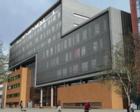
Part of the Keyworth II development at London’s South Bank University is an energy centre that will provide a focus for research, teaching and demonstration of environmentally sustainable energy systems in buildings. Note the stainless-steel mesh on the façade to reduce solar gain.
With London South Bank University being a key centre for building-services engineering in the UK, it is appropriate that a major new development should seek to be a benchmark for sustainable future developments. Its designed emissions of carbon dioxide are little more than half of what are required by Building Regulations.Keyworth Street will be familiar to thousands of engineers in the building-services industry as a main thoroughfare on the site of London South Bank University, where they earned their degrees. Now a new building is going up, Keyworth II, with strong sustainability aspects that will provide a benchmark for future developments. Part of the project is an energy centre that will provide a focus for research, teaching and demonstration of environmentally sustainable energy systems in buildings. The Keyworth II building will house the faculty of health and social care, department of education and facilities for sports science. It replaces the former student-union building and the former George pub. This flagship building is designed by architects Grimshaw with FaberMaunsell as consulting engineer. The main contract was awarded in August last year, and completion is expected early in 2009. A key feature of the building is the geothermal energy pile, which will be the largest of its type in London when completed. The thermal capacity of the concrete structure will be used to improve the energy efficiency of the building. Building-services systems are designed to have very low carbon-dioxide emissions and include ground-coupled heat pumps for heating and cooling, solar-thermal water heating, energy recovery on all systems and geothermal loops integrated in piles. The integrated design approach will deliver a high-performance building with low dependence on mechanical systems. Extensive façade engineering undertaken with Grimshaw will help to deliver an L2A compliance of over 60%. This 9000 m2 teaching and research facility includes four lecture theatres, each with a capacity of 80 to 130 students, with associated spaces to gather and wait before and after lectures. There is also a cafeteria, meeting and event space.
Environmental strategy Close co-ordination with the architectural and structural teams has been of paramount importance in defining the building’s massing and form. The building-services strategy is encapsulated within the total building solution to provide an energy-efficient system whilst maintaining environmental conditions under seasonal and occupiers’ conditions.
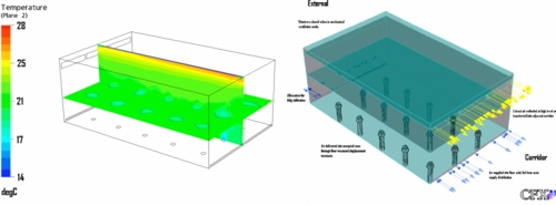
Air distribution Supply air is conditioned through roof-mounted air-handling units incorporating hygroscopic thermal wheels capable of transferring heating and cooling energy and and latent recovery. Tempered air from the roof mounted AHUs is ducted to builders’ work risers and one ducted riser serving the main block and back-pack, respectively. From the risers, supply air is ducted at low level to pressurise the floor-void plenum. Supply air is delivered at low level into the conditioned space via floor grilles from the pressurised plenum. The principle of this system is based on low-momentum air supply and natural convection generated by the buoyancy of the heat sources in a space. The supply air is cooler than room temperature and discharged at low velocity, low momentum and low turbulence through high-induction floor outlets into the occupied space.
 |
Computational fluid dynamics was used to predict internal conditions in a classroom of the Keyworth II development. Cool air enters the room from the floor-void plenum through high-induction floor outlets into the occupied space. Return air enters the corridor through high-level attenuator, from where it is returned to central air-handling plant. |
Return air is transferred from the occupied rooms into the corridor via high-level attenuators mounted above the doors. The return air then travels down the corridor and is returned to the central air-handling plant via high-level extract grilles in the builders’ works risers. At the air-handling plant, the thermal wheel recovers energy.
Thermal environment The environmental systems utilise the thermal mass of the concrete structure to improve the energy efficiency of the building. The building’s thermal mass act as a thermal sponge, absorbing heat from the building during the summer to cool it and storing heat from the Sun or heaters to be released at night during the winter. To determine the requisite air quantities and temperatures and to monitor air flows, a single class- room has been modelled using computational fluid dynamics (CFD) software to predict internal conditions under predetermined situations. The façade has been engineered to control and limit solar gains to protect the internal environment. Utilising an outer cladding of 40% stainless-steel mesh, optimum solar reduction is achieved. CFD results showed that internal heat gain starts to increase from 50% mesh area upwards because the density of the mesh limits air movement, resulting in a build up of heat between the inner skin of the mesh and the façade, resulting in higher radiant gains.
Renewables All building heating and cooling demand is satisfied from the geothermal energy pile system, utilising the constant temperature of the ground beneath the building, which is typically 10 to 14°C in the UK. Liquid similar to antifreeze is circulated through a closed pipework system within the structural piles, and is controlled by four 125 kW reversible heat pumps connected to the secondary circuit serving the building’s heating and cooling requirements.
Solar hot water The solar-hot-water system is predicted to reduce carbon-dioxide emissions by 2.7 to 5.7% utilising evacuated solar tubes on the roof of the energy centre. This system will support the direct-gas-fired domestic-hot-water system. Part L2A Carbon emissions are capped by creating a target emission rate for carbon dioxide (TER). The predicted carbon-dioxide emissions from the actual building design are known as the building emission rate (BER) and may not exceed the TER. The TER is calculated by modelling a notional building of the same size, shape and use as the proposed building, but with 2002 Building Regulation energy performance values. Energy-efficiency improvements and low- and zero-carbon energy sources are then applied to the notional building to calculate the reduction in emissions reduction required from the notional building. The BER is calculated by using the same calculation tool as used for establishing the TER. The final calculation takes into account any changes to specification made during construction and the measured air tightness on commissioning. The TER for the Keyworth II building has been calculated at 32 kg/m2 of carbon dioxide a year, based on the notional building of 43 kg/m2 per year. Implementing the energy-saving strategies described above, the BER has been calculated as 16.7 kg/m2 of carbon dioxide per year — a 61% improvement over the notional building.
Related articles:


