Step by step to MVHR

Penny Jones runs through the stages of installing an MVHR system to ensure good performance
Mechanical ventilation and heat recovery (MVHR) systems are increasingly popular as part of domestic installations. They help to improve indoor air quality, making for a more comfortable and healthier home environment. What’s more, they can also provide up to 50% savings on energy bills due to reduced heating demand.
The example shown here is the Domus Ventilation HRXE range, suited small to medium size residential properties. Measuring 507mm (h) x 356mm (d), it is a compact unit designed for cupboard installation. This can be done on-site, or in pre-fabricated modular construction projects.
 |
| Image 2 |
Identify the location for the MVHR unit
A clear working space is required around the installed unit to allow the cover to be removed and provide sufficient access for maintenance such as filter change. Allow a minimum of 350mm in front of the unit. The fan must be installed indoors, on a suitable wall away from direct sources of frost, heat and water spray or moisture generation.
The MVHR unit is designed to extract air from all wet rooms e.g. bathroom, kitchen, utility room (with sink). Supply air should be to all habitable rooms e.g. bedrooms and lounge.
Install and seal ducting
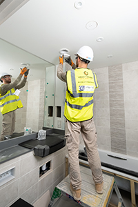
(Image 1) Round or flat channel rigid duct should be used and held in place with a support strap every 750mm. Alternatively, semi-rigid radial ducting systems are a great way of reducing install time on site. Ducting must be installed in such a way that resistance to airflow is minimised, with bends kept to a minimum. A minimum distance of 300mm between the MVHR appliance and any bends in ductwork is recommended. Seal ducting joints with silicone type sealant such as DDSEAL.
 |
| Image 3 |
Fit insulation to ducting
The government’s Domestic Ventilation Compliance Guide includes a standard for ducting insulation. It should be installed on the outside of the external air inlet duct and the air outlet duct from the unit, to prevent condensation.
Install grilles
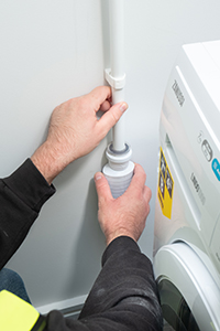
(Image 2) Extract / input grilles should be valves which are adjustable for commissioning. External grilles are to have a minimum free area of 12,250 mm2.
Fix the mounting bracket for MVHR Unit
Fix the mounting bracket to a solid wall, ensuring the interlock side is at the top. If it’s not practical to use a solid wall, the MVHR unit should be fixed to a stud partition with a 25mm minimum thickness MDF panel solidly fixed behind the plasterboard.
 |
| Image 4 |
Wall mount the MVHR unit and connect to power supply
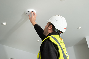
Install the unit on the wall by ensuring the bracket fixed to the rear of the unit interlocks over the wall mounted bracket. The cable from the mains power supply should be connected to a fixed wiring installation, via a fused isolator, in accordance with current IEE Wiring Regulations. For good EMC engineering practice, any sensor cables or switched live cables should not be placed within 50mm of other cables or on the same metal cable tray as other cables. The unit must be earthed.
Connect condensate drain and check filters
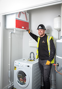
(Image 3) If the condensation pipe is fitted in an unheated space the pipe should be insulated. Prior to commissioning, take the protective film off the filters and replace. Ensure they are dust and debris free.
 |
| Image 5 |
Commissioning and post-commissioning
(Image 5) A calibrated moving vane anemometer and hood are required to carry out commissioning. Adjustment valves should be locked in place to prevent further adjustment. The clear panel covering the control has an adhesive panel which should be exposed and sealed post commissioning to prevent tampering.
As simple as that!
(Image 5) One happy installer, one happy developer and one soon-to-be happy home owner.
Penny Jones is product and marketing Manager at Domus Ventilation
