Condensing Your Design

As energy targets and legislative requirements tighten, low carbon equipment like CHP is increasingly integrated into multi-component solutions for compliance with Building Regulations.
Ryan Kirkwood considers the various design options and how to reap the full financial and environmental rewards
In non-domestic buildings with high, constant heat requirement – such as hospitals, leisure centres, student accommodation schemes and schools with extended occupancy hours – one technology that continues to provide compelling economic advantages is combined heat and power (CHP).
CHP works by generating lower-cost electricity and high-grade heat on site in a single highly-efficient process. As such, it offers scope for financial savings in the region of 30% and improved environmental performance compared with relying on traditional heating plant and electricity supplied solely from the grid. And pairing CHP with high-efficiency condensing boilers is an effective means of ensuring that the system performs to its full potential, reducing operational costs while generating electricity at lower gas prices.
So why do we still hear reports of CHP systems that fail to deliver the anticipated benefits?
To answer this, it’s important to note that a CHP unit only delivers savings when it’s running. Hence the repeated advice to carry out a feasibility study, check the heat and power demand profiles, and avoid oversizing at all costs.
But a CHP cannot be considered in isolation – good integration with the system (and, in this case, the condensing boilers) is essential to optimise system performance. The design must therefore ensure that the CHP unit operates as the lead ‘boiler’ and that the condensing boilers are not brought on too early.
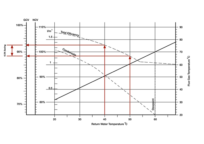
When are condensing boilers at their maximum efficiency? When they can operate in full condensing mode. For this to take place, the return water temperature needs to be at or below dew point, which is normally around 54°C.
Depending on the temperature difference, boiler efficiency could be increased by as much as 9.5%. Even lowering the return water temperature by just 10°C would increase boiler efficiency by around 4.5% (see chart below).
 |
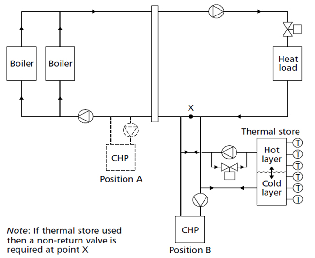
Let’s consider the various methods of integrating a CHP unit with condensing boilers. The most common means of ensuring that the CHP sees the load first is to use a series method where the CHP preheats the return (see Graphic 1).
This has the advantage that the CHP will remain at maximum output at high demand and will always receive a constant flow of water. Connection in series is commonly used on retrofit projects with position B being the preferred point to avoid any recirculation via the Low Loss Header (LLH).
Graphic 1: CIBSE CHP Series
 |
The disadvantage of this method is that preheating the return water back to the boilers could have an impact on the boilers’ ability to condense. On average we can expect a marginal lift of this return temperature at full load as the CHP mass flow rate is small compared to the system return volume. However, during part load, we can see a large increase in the overall return temperature back to the boilers.
The example below shows the CHP sized at approximately 10% of thermal peak load of the building.
Graphic 2: FULL LOAD – 2.2°C lift in return temperature to boiler
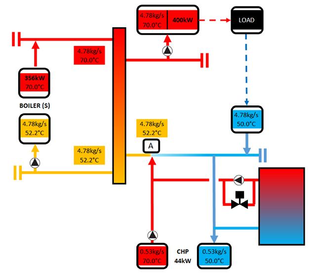 |
In the full load example in Graphic 2, the boilers are receiving return water below 55°C, which allows the boilers to condense, but at 52.2°C rather than 50°C. This decreases efficiency.
Graphic 3: PART LOAD – 10°C lift in return temperature to boiler – non condensing
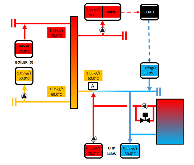 |
In the part load example in Graphic 3, the boilers are receiving return water over 55°C, which removes the efficiency advantages from condensing operation
Parallel connection
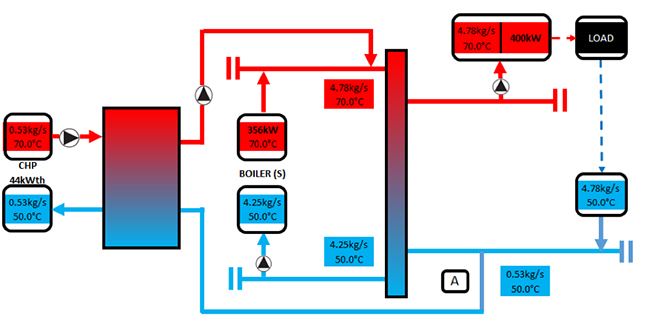
How, then, to engineer around this? An alternative method is to connect the CHP in parallel with the boilers, but with a separate return used exclusively for the CHP.
Graphic 4: FULL LOAD – boiler and CHP receive system load return temperature
 |
Graphic 5: PART LOAD – no lift in return water to boilers
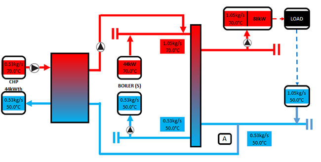 |
Using this method, the boilers’ return temperatures are not affected by the CHP and, using the same values given above, the boiler will always see the true load return temperature no matter the load or the CHP size.
This methodology allows for full condensing operation of both the CHP and the boilers throughout the entire load range without sacrificing the efficiency of either unit. It is important however that:
• the CHP acts as lead boiler
• the buffer tank is configured in either 2 or 4 port pending system loading
• the boilers are not fired too early during periods of high demand.
As with any design, the control strategy is key as it will ensure that the CHP runs as the lead boiler, thereby maximising its operating hours and the financial returns.
The buffer or thermal store really comes into its own when using a split return parallel method. Rather than simply being a thermal mass to increase system volume, it can be used to support peak loads, thereby increasing the overall kWh output delivered by the CHP.
During periods of high demand, the thermal store discharge pump can deliver more energy into the system than the CHP alone can put in, for a finite amount of time. How much energy and for how long will depend on the storage temperature held and the buffer size. This in turn will be determined by practical and physical plant room limitations. A 1,000 to 2,000 litre buffer is typically the most practical option for most commercial buildings suitable for CHP.
As the usable temperature layer within the buffer drops to a critical level, the discharge pump will need to retort back to an equal kW output to the CHP to prevent the store’s usable flow temperature from dropping below target system flow.
If this were to happen, the boiler flow would blend with the thermal store prior to entering into the LLH. Slightly elevating the boiler temperature would ensure that target system temperature is reached, although avoiding this scenario is preferable.
What advantages does this design bring to the system? It allows the CHP more freedom to track the building’s load during the day. Being able to discharge and charge the buffer during the day as the loads go up and down can and will hold off boiler operation as much as possible, delivering more savings and performance for the end user.
Sizing the CHP on a peak load or to meet compliance requirements (above that of base load) will result in periods of demand below CHP turndown during summer or transient days, which is a situation best avoided. We therefore recommend sizing the CHP on base load to ensure maximum run hours and prevent cycling of the CHP unit, with the boilers meeting peak or steady state demands in winter months.
It is important to note, however, that these designs only focus on the thermal output of the CHP. While the practice of controlling CHPs on an electrical rather than a thermal demand is increasing, this generally involves heat discharge direct to atmosphere, negating the full benefits of CHP.
When it comes to hybrid CHP and condensing boiler systems, ask yourself these three critical questions:
• Is the CHP providing as much usable energy as possible?
• Is the CHP condensing?
• Are the boilers condensing?
Get that right, and the financial and environmental rewards will follow.
Ryan Kirkwood is Specification Manager for Remeha
